

COMBUSTING KATALIZATOR APPLICATION TEST
ON INLAND WATERWAY
SUPLEMENT
AUTHOR OF THE TEST
Dr. Eng. Wojciech Ignalewski
SZCZECIN, 2016
Introduction
The analysis and research were carried out for the purposes of developing techniques and technologies to reduce the emission of harmful substances into the atmosphere emitted by inland vessels. The study was based on the use of a catalytic installation, which may be one of the directions of adapting the unit to emission standards as an alternative to modernizing and replacing the ship’s power plant.
The REDUX KATALIZATOR was used as an additive to hydrocarbon fuels and an active substance that reduces the surface tension of carbon causing complete combustion of soot and naphthalenes.
The catalyst does not deteriorate the physicochemical properties of the fuel, reduces the emission of PM (soot), HC hydrocarbons and carbon monoxide CO. Under the influence of the action, the chain reaction rate of the combustion process changes. Used in diesel engines, it reduces fuel consumption from 4% to 12% depending on the engine operating point. REDUX is a selective catalyst with approximate empirical formula: C5H5FeC5H4COCmHn
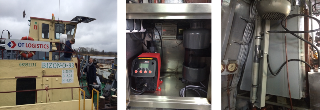
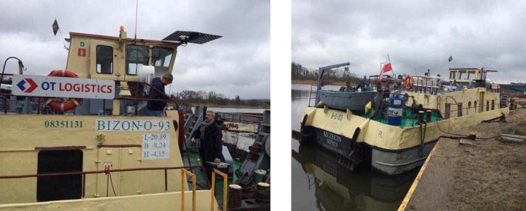
The study was preceded by a prototype installation dedicated to an inland ship. The research unit was the Bizon 0-93 pusher with the number 08351131 (L = 20.89 / B = 8.24 / H = 4.15). The results of the study were made based on the requirements of ISO standards.
The introduction of restrictions on the sulfur content of fuels used in shipping under Annex VI to the International Convention for the Prevention of Pollution from Ships (MARPOL) is a defiance for the European shipping environment.
In July 2015, the Regulation of the European Parliament and the Council of the European Union 2015/757 of 29 April 2015 entered into force, on the monitoring, reporting and verification of carbon dioxide emissions from maritime transport and the amendment of Directive 2009/16 / EC, as the first act of European law obliged maritime industry entities to apply information procedures in the field of CO2 emissions. This Regulation entered into force in 2017. Due to the link between maritime transport and inland waterway transport, emission reductions apply directly to this sector.
The Regulation of the Minister of Economy of 30 April 2014 on detailed requirements for internal combustion engines in the scope of limiting the emission of gaseous and particulate pollutants by these engines contains guidelines for testing the content of carbon dioxide and carbon monoxide in the exhaust gas of inland vessel engines. The emission limits for gaseous pollutants, given for individual categories depending on the net power, for inland watercraft engines are specified in stage IIIA.
The principles of the study were based on the procedure and conditions of the NRSC test. The test cycle consists of a set sequence of assumed speed and load phases that should cover the typical engine operating range.
The use of installations with REDUX catalyst reduces the emission of substances into the atmosphere, it should be emphasized that their emissions are within the range of current and future standards, which entered into force in 2017.
The results laboratory tests have shown that REDUX is characterized by the following specificity:
- Particulate matter (PM) emission reduction in the entire engine load range in within 53-73%;
- Decreased emission of insoluble organic fraction (SOF) in the range of 35-62%;
- Decrease in particulate emissions (PM = S + SOF) in the range of 40-62%;
- Decrease in unburned hydrocarbon emissions in the range of 19-40%;
- Carbon monoxide CO emissions reduced at very low loads by 38% in the remaining 1-9%;
- The decrease in fuel consumption in the engine from 4 to 12% depending on the engine operating point;
- A 90% decrease in CO emissions at 1000 rpm and a reduction of nearly 74% PM emissions;
- HC hydrocarbon emissions drop to 30%
In addition, the use of REDUX catalyst affects:
- Reduction of combustion products entering the lubrication system,
- No deposition of unburned parts like carbon deposits in the combustion chamber,
- Increasing the amount of thermal energy (work),
- Removal of petroleum bacteria,
- Reduction of particulate emissions (PM) in exhaust gases.
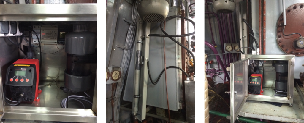
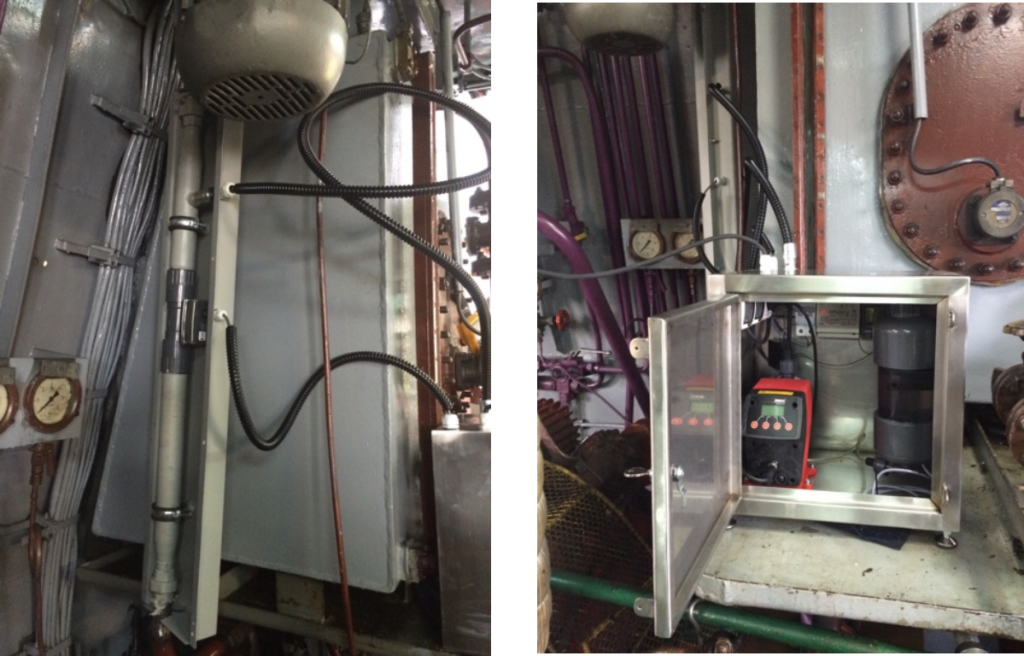
Installation components on the BIZON 0-93 inland ship for REDUX catalyst
- Gravity catalyst tank
- Pump
- Pump power cord (230V)
- Reserve level sensor (100ml)
4.1. Cable transferring information about the reserve level to the pump
- Gravity catalyst tank
- Pump
- Pump power cord (230V)
- Reserve level sensor (100ml)
4.1. Cable transferring information about the reserve level to the pump - Flow sensor
5.1. Conduit transferring information on fuel flow to the pump - Spring injector
- Cable sheath
- Butterfly valve
- Catalyst line
- Proposed valve assembly with adjacent components
- Catalyst tank clamp
The scheme of working fluid flow
- The refrigerant is placed from the outside in the gravity tank
- Fluid flow through the pipe to the pump
- Pump pressure
- Fluid flow through the pipe from the pump to the injector
- Refrigerant injection into the fuel line with a spring injector
- Fluid flow through the fuel line together with the fuel
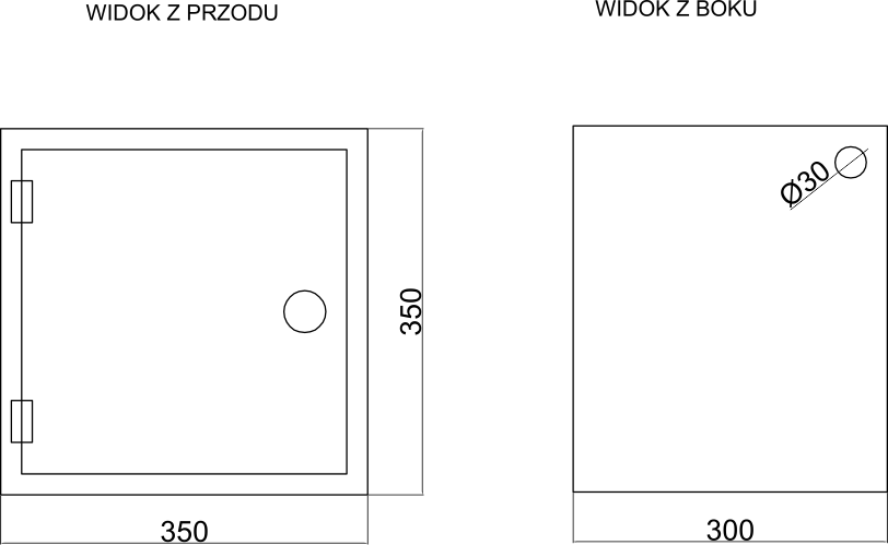
INSTALLATION SCHEME


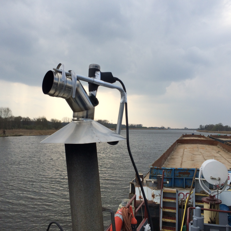
ZABUDOWA ZEWNĘTRZNA INSTALACJI
1. Pomiary wykonane bez zastosowania REDUX KATALIZATOR
1.1. Cykl pomiarowy I
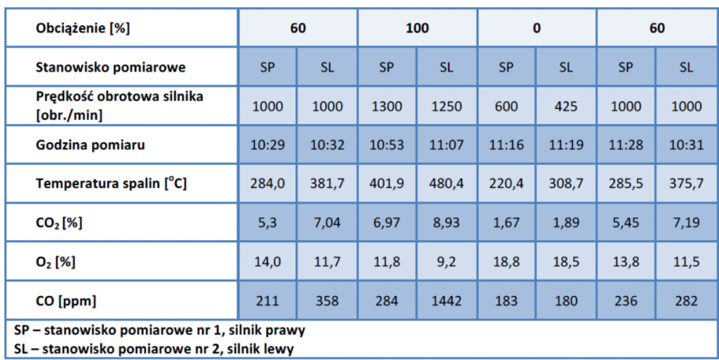
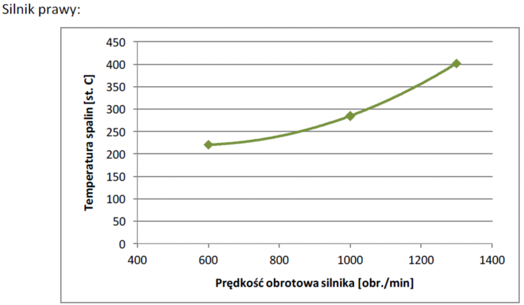
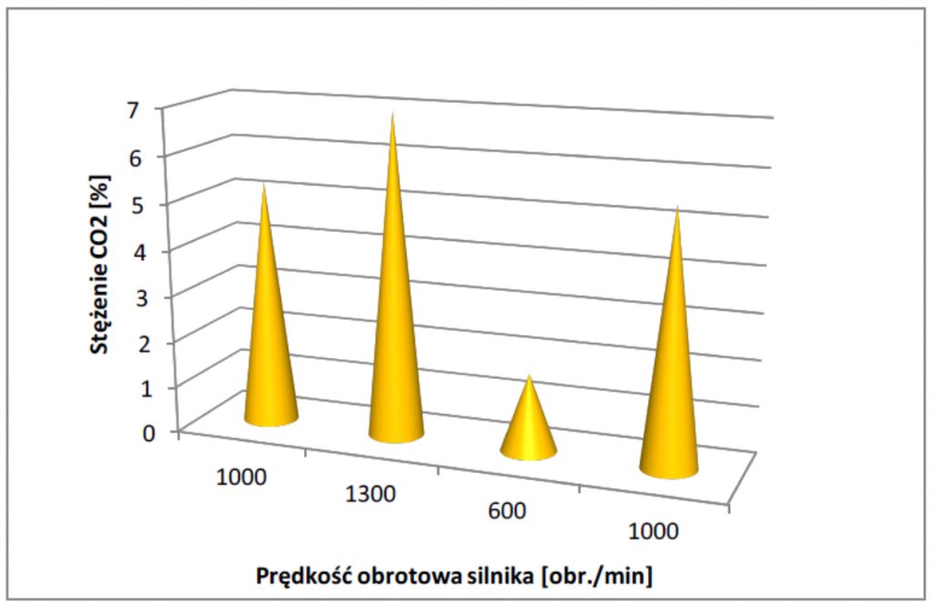
1.2 Cykl pomiarowy II
PRÓBA POMIARU PO ZASTOSOWANIU
REDUX KATALIZATOR
Rozporządzenie Ministra Gospodarki z dnia 30 kwietnia 2014 r. w sprawie szczegółowych wymagań dla silników spalinowych w zakresie ograniczenia emisji zanieczyszczeń gazowych i cząstek stałych przez te silniki zawiera wytyczne do przeprowadzenia badań zawartości dwutlenku węgla oraz tlenku węgla w spalinach silników jednostek śródlądowych.
Wartości graniczne emisji zanieczyszczeń gazowych, podawane dla poszczególnych kategorii w zależności od mocy netto, dla silników jednostek śródlądowych, określone są w etapie IIIA.
Zasady przeprowadzonego badania zostały oparte o procedurę i warunki testu NRSC. Cykl takiego testu składa się z ustalonej sekwencji założonych faz prędkości i obciążenia, które powinny pokryć typowy zakres pracy silnika.
Zgodnie z rozporządzeniem badanie powinno składać się z czterech faz, dla obciążenia:
100%, 75%, 50% i 25%. Ze względu na specyfikę warunków badań – nie były to badania laboratoryjne na hamulcu dynamometrycznym ale badanie zostało przeprowadzone w warunkach rzeczywistych, na pracującej jednostce śródlądowej, przyjęto następujące fazy:
- Faza obciążenia maksymalnego – osiągane i utrzymywane są obroty maksymalne;
- Faza obciążenia średniego – utrzymywana jest wartość 1000 obr./min;
- Faza biegu jałowego – nie jest podawane obciążenie, silnik działa na wolnych obrotach.
| Nr fazy | Obciążenie | Prędkość obrotowa | Współczynnik wagowy |
| 1 | 60% | 1000 | 0,15 |
| 2 | 100% | 1300 | 0,15 |
| 3 | 0% | 500 | 0,7 |
Współczynnik wagowy przyjęto ze względu na czas pracy silnika przy określonym obciążeniu
w normalnym trybie eksploatacji.
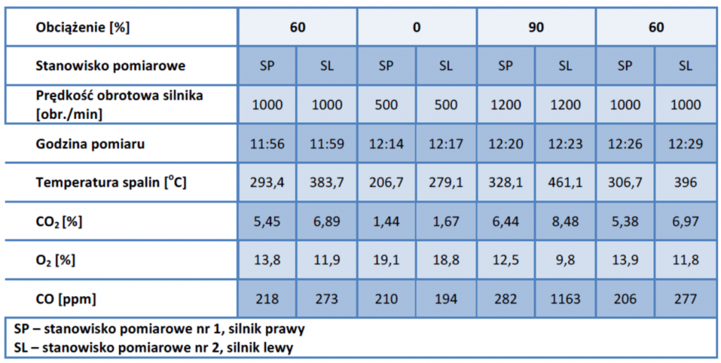
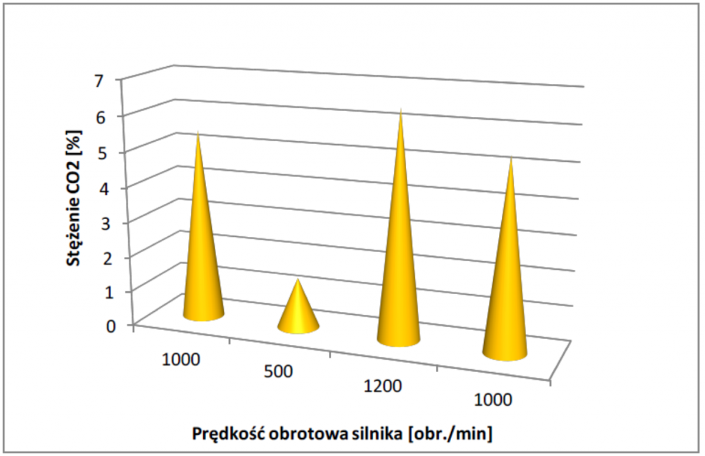
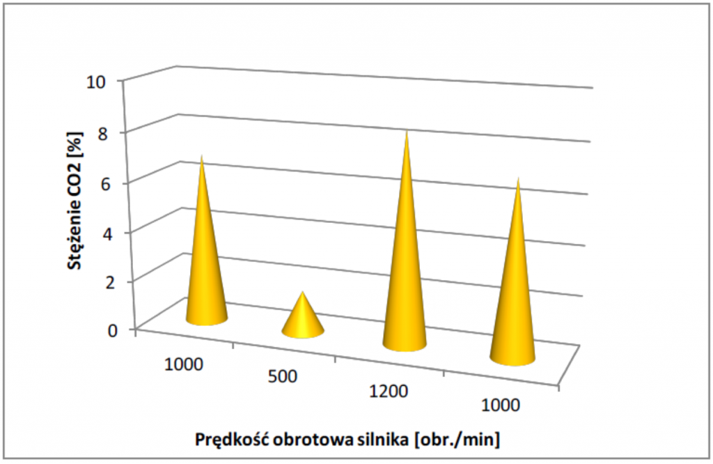
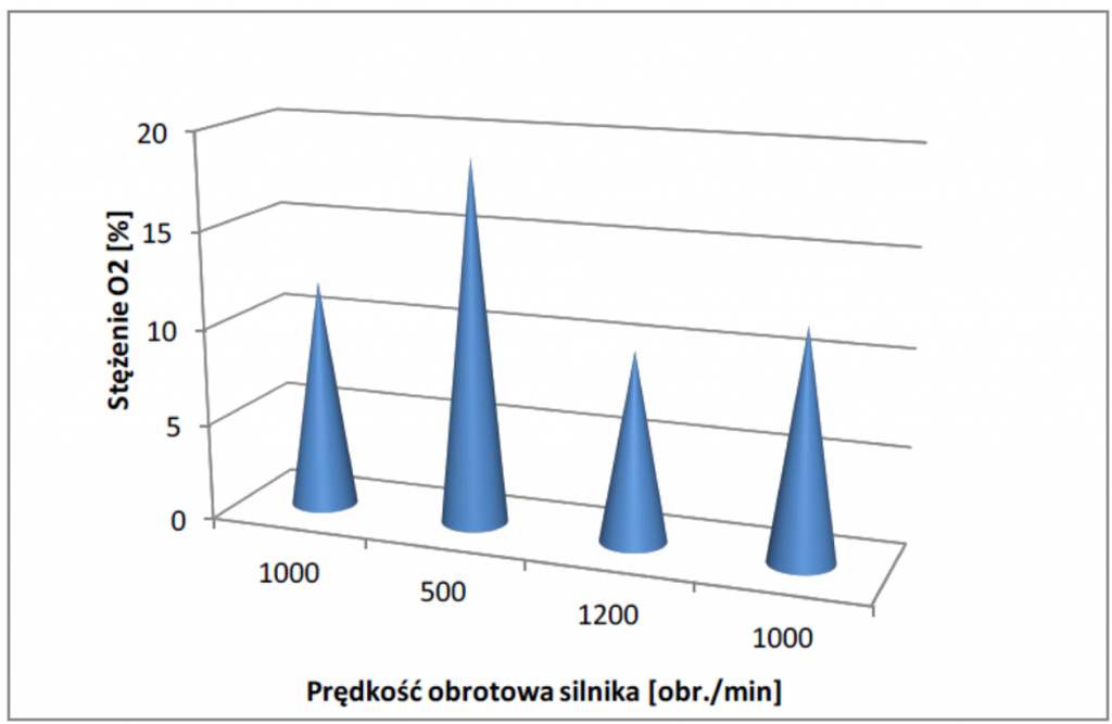
Określono stężenie badanego składnika spalin dla każdej fazy.
Rozpoczęcie badań nastąpiło po rozgrzaniu silnika do osiągnięcia stabilizacji wszystkich parametrów (temperatury i ciśnienia) przy określonym obciążeniu. Przepływ spalin przez analizator trwał około 3 minut – do całkowitego ustabilizowania się wyników podawanych na wyświetlaczu analizatora.
W dniu 31.03.2016 oraz w dniach 05.04.2016 do 14.04.2016 przeprowadzono pomiary emisji przed i po zastosowaniu środka – Redux katalizator. Przeprowadzone badanie zostało wykonane w oparciu o dopuszczoną metodykę wykonywania pomiarów w niniejszym rozporządzeniu. Rozporządzenie Ministra Gospodarki z dnia 30 kwietnia 2014r. w sprawie szczegółowych wymagań dla silników spalinowych w zakresie ograniczenia emisji zanieczyszczeń gazowych i cząstek stałych przez te silniki zawiera wytyczne do przeprowadzenia badań zawartości dwutlenku węgla oraz tlenku węgla w spalinach silników jednostek śródlądowych.
Zasady przeprowadzonego badania zostały oparte o procedurę i warunki testu NRSC. Cykl testu składa się z ustalonej sekwencji założonych faz prędkości i obciążenia, które powinny pokryć typowy zakres pracy silnika. Silniki były zasilane z jednego bunkrowania.
Podstawowe dane układu napędowego jednostki
| Wola 05H6Aa | |
| moc nominalna | PB=139 kW |
| sprawność przeniesienia napędu | ηTR=0,91 |
| obroty nominalne silnika | ns=1500 min-1 |
| przełożenie przekładni | i=4 |
| pędnik Ka4-55 w dyszy 19A | |
| średnica | D=1,26 m |
| współczynnik skoku | P/D=0,778 |
| współczynnik ssania | t=0,2 |
| współczynnik strumienia nadążającego | w=0,3 |
Napęd statku stanowią dwa sześciocylindrowe silniki główne typu 05H6Aa na licencji Wola Henschel, o mocy nominalnej 190KM przy obrotach nominalnych ns=1500 min. Jednostopniowa przekładnia redukcyjno nawrotna Wola 4R-20 daje przełożenie 4:1.
Zgodnie z rozporządzeniem badanie powinno składać się z czterech faz, dla obciążenia:
100%, 75%, 50% i 25%. Ze względu na specyfikę warunków badań – nie były to badania laboratoryjne na hamulcu dynamometrycznym ale badanie zostało przeprowadzone w warunkach rzeczywistych, na pracującej jednostce śródlądowej, przyjęto następujące fazy:
- Faza obciążenia maksymalnego – osiągane i utrzymywane są obroty maksymalne;
- Faza obciążenia średniego – utrzymywana jest wartość 1000 obr./min;
- Faza biegu jałowego – nie jest podawane obciążenie, silnik działa na wolnych
obrotach.
| Nr fazy | Obciążenie | Prędkość obrotowa | Współczynnik wagowy |
| 1 | 60% | 1000 | 0,15 |
| 2 | 100% | 1300 | 0,15 |
| 3 | 0% | 500 | 0,7 |
Współczynnik wagowy przyjęto ze względu na czas pracy silnika przy określonym obciążeniu
w normalnym trybie eksploatacji.
Określono stężenie badanego składnika spalin dla każdej fazy.
Rozpoczęcie badań nastąpiło po rozgrzaniu silnika do osiągnięcia stabilizacji wszystkich parametrów (temperatury i ciśnienia) przy określonym obciążeniu. Przepływ spalin przez
analizator trwał około 3 minut – do całkowitego ustabilizowania się wyników podawanych w analizatorze.
Podczas prób wykonano 80 pomiarów na obu silnikach jednostki, w tym w okresie 05-14.04.2016 z zastosowaniem czynnika – Redux katalizator.
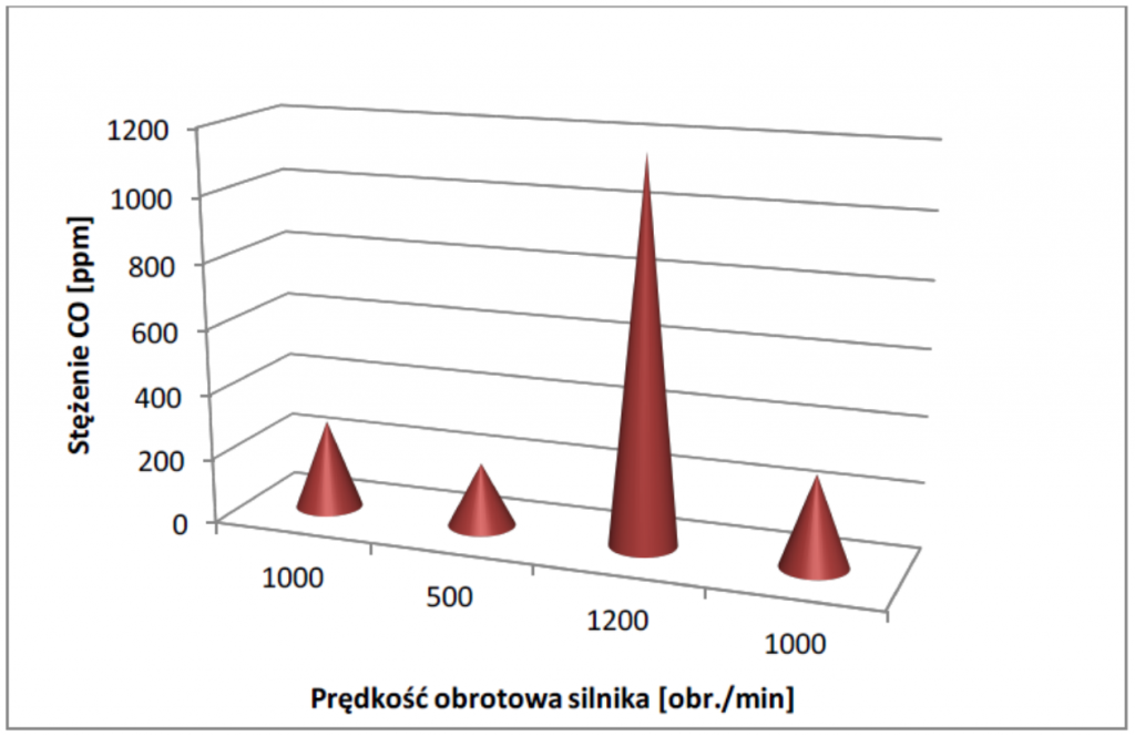
Analiza wykazała:
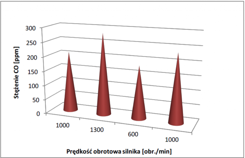
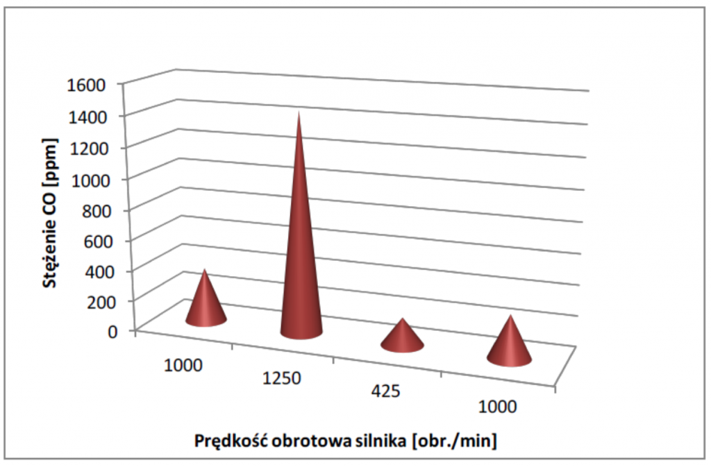
- Na silniku L spadek tlenku węgla (CO) z 919 ppm do 389 ppm (~236%);
- Na silniku L spadek tlenku nieroz. z 2031 ppm do 939 ppm (~216%);
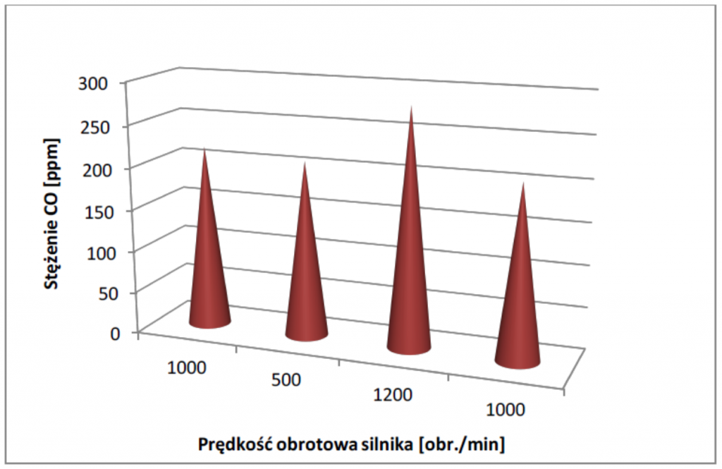
- Na silniku P spadek tlenku węgla (CO) z 920 ppm do 337 ppm (~272%);
- Na silniku P spadek tlenku nieroz. z 1952 do 753 ppm (~259%).
- Pomiar nr 1 (NO) wyniósł 1400 ppm, pomiar ostatni 37 w tym zakresie 755 ppm,
co stanowi spadek o 47% w stosunku do pomiaru bazowego.
PRZYKŁAD KARTY POMIAROWEJ 1
| Data: | 05.04.2016 | 14.04.2016 |
| Godzina pomiaru: | 09:13:59 | 15:00:13 |
| Pomiar nr: | 1 | 80 |
| Silnik (prawy/lewy) | P | P |
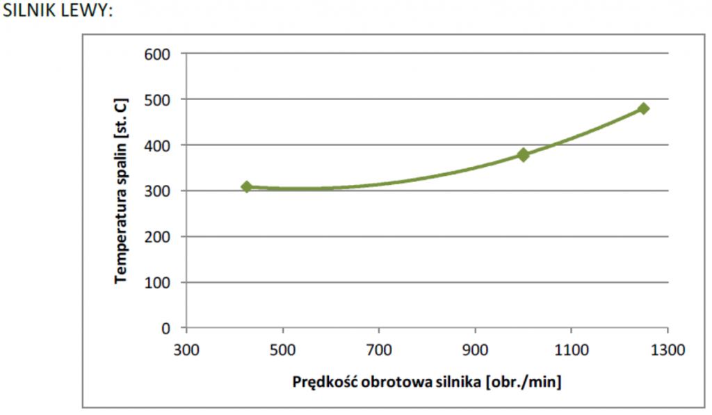
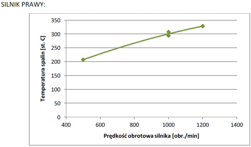
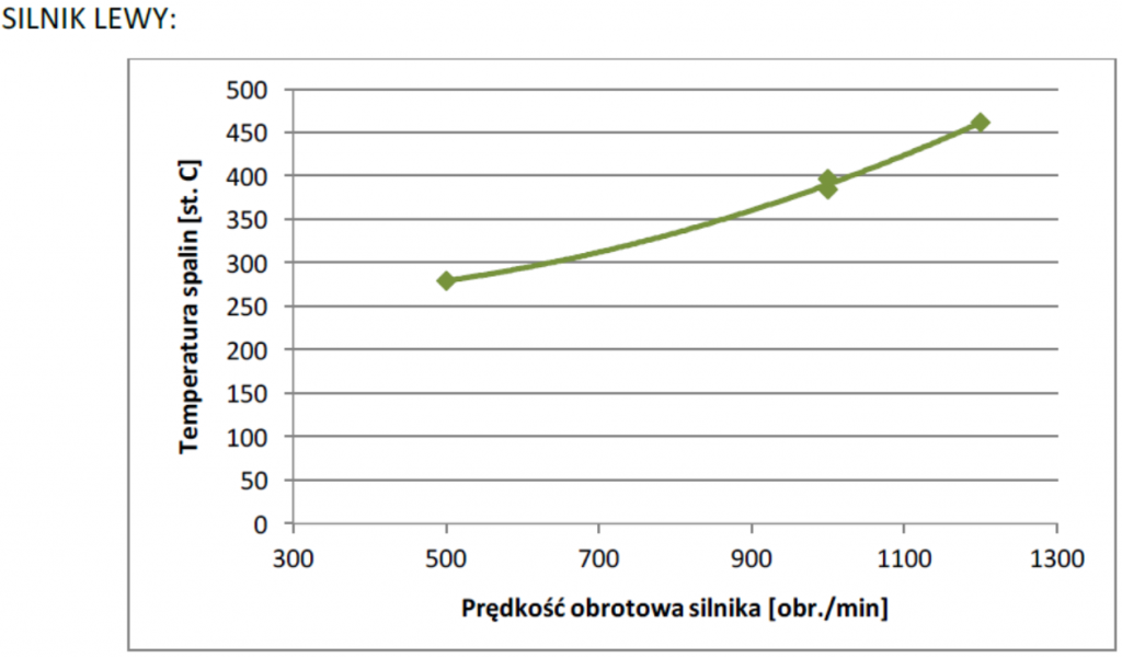
| Temperatura spalin – stopień C | 272,5 | 378,4 |
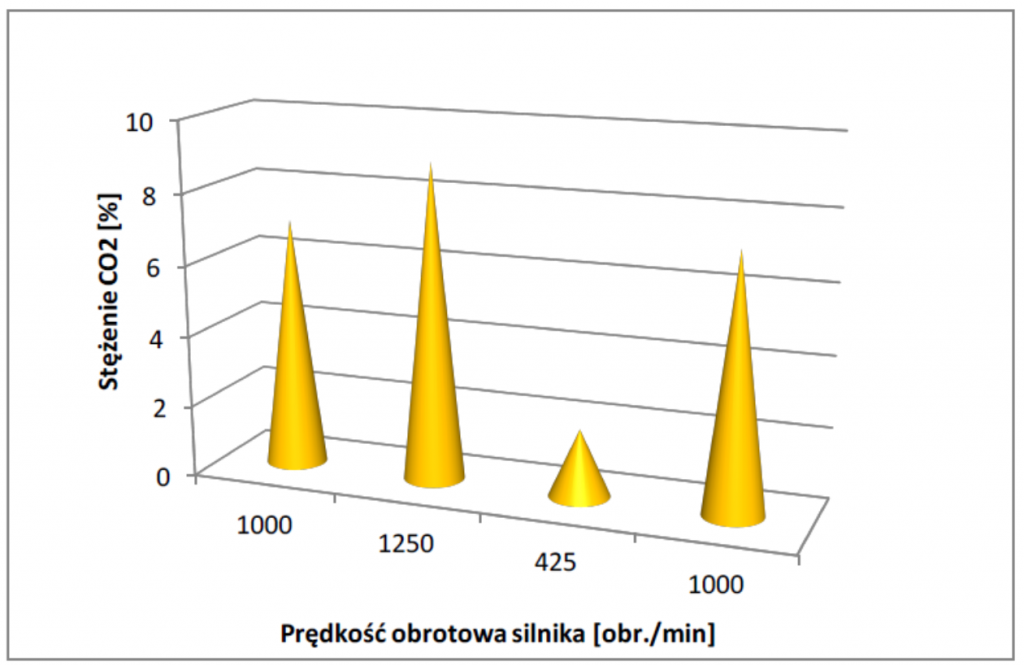
| Dwutlenek węgla (CO2) – % | 7,26% | 7,12% |
| qA b – % | 19,5 | 30,8 |
| Lambda | 2,12 | 2,23 |
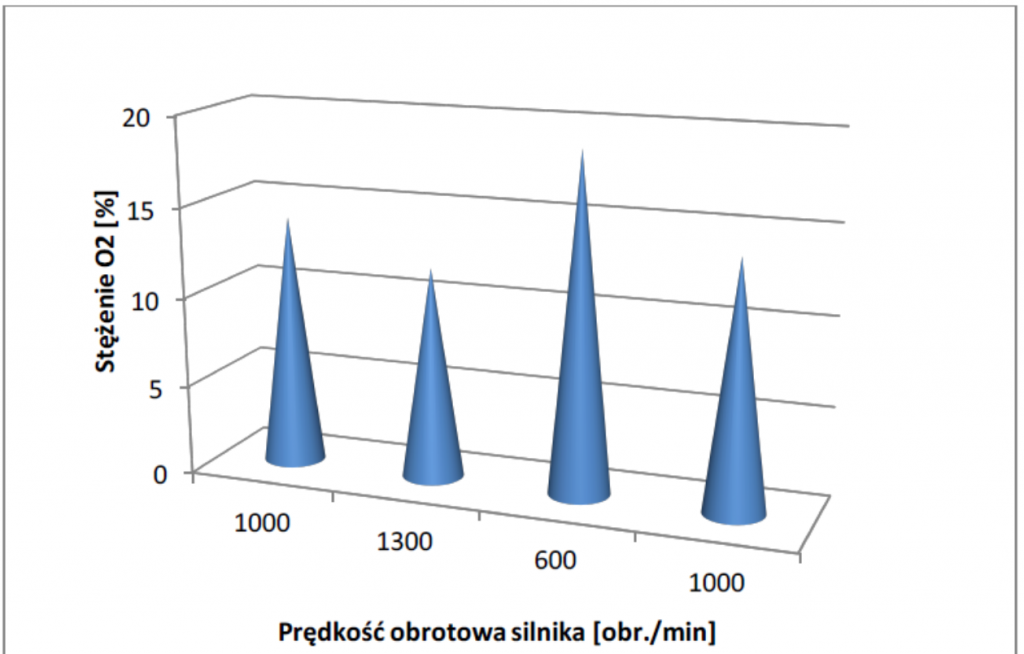
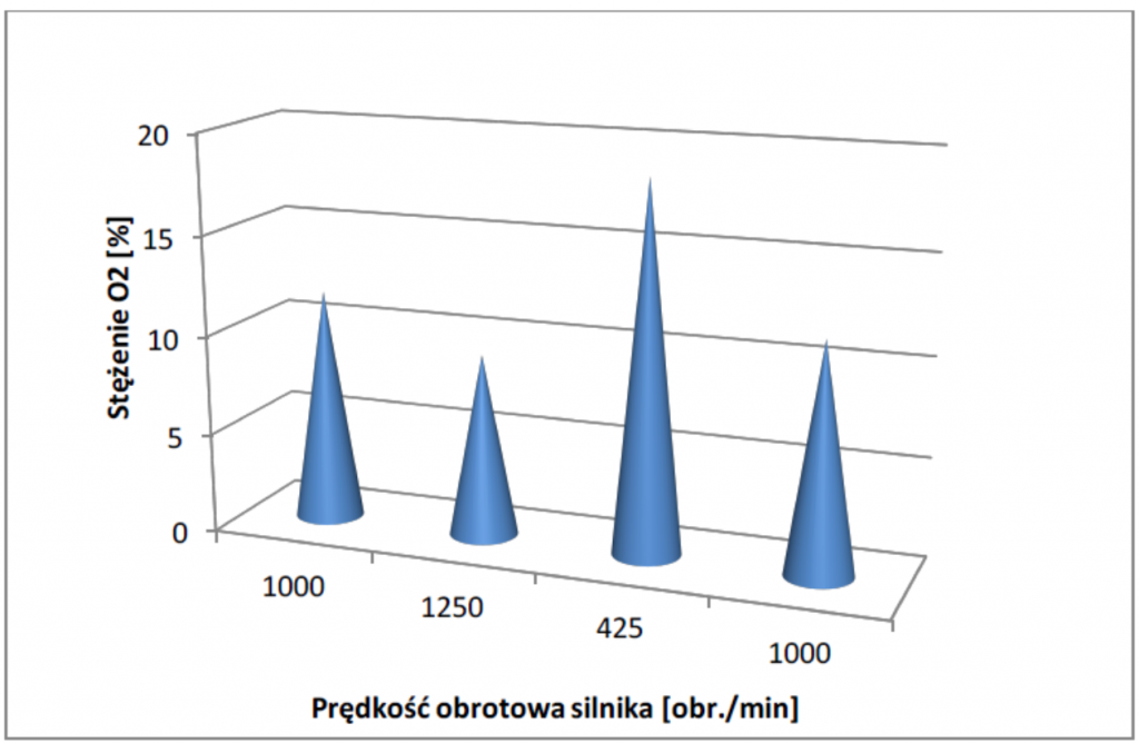
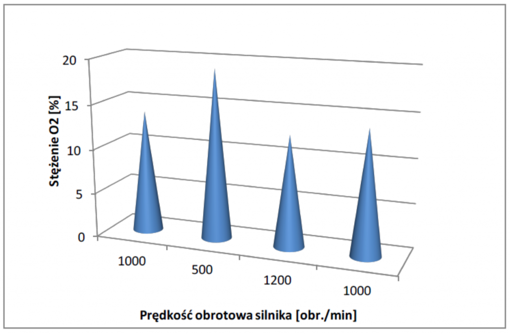
| Tlen – % | 11,1 | 11,6 |
| Tlenek węgla (CO) – ppm | 920 | 337 |
| CO nieroz. – ppm | 1952 | 753 |
| Sprawność – % | 80,5 | 69,2 |
| Temperatura powietrza – stopień C | 14,2 | 18,8 |
| O2 pds – % | 11,1 | 11,6 |
| Punk rosy – stopień C | 39,9 | 38,9 |
PRZYKŁAD KARTY POMIAROWEJ 2
| Data: | 05.04.2016 | 14.04.2016 |
| Godzina pomiaru: | 09:15:54 | 15:00:13 |
| Pomiar nr: | 4 | 77 |
| Silnik (prawy/lewy) | L | L |
| Temperatura spalin – stopień C | 337,7 | 386 |
| Dwutlenek węgla (CO2) – % | 6,97% | 6,59% |
| qA b – % | 25,4 | 33,9 |
| Lambda | 2,21 | 2,41 |
| Tlen – % | 11,5 | 12,3 |
| Tlenek węgla (CO) – ppm | 919 | 389 |
| CO nieroz. – ppm | 2031 | 939 |
| Sprawność – % | 74,6 | 66,1 |
| Temperatura powietrza – stopień C | 14,4 | 19,9 |
| O2 pds – % | 11,5 | 12,3 |
| Punk rosy – stopień C | 39,3 | 38,2 |